


Hi Gang…
It’s interesting to look back and think about what was “old” and what was “modern” in the 50s. If you were building a car in the mid 1950s, the current “state of the art” was a column shifter. In fact, if you were using Ford components, they had changed from floor shifting transmissions to column shifting transmissions in 1940.
So in a way, if you wanted a floor shifter for your sports car, you were making your car seem “older” and not necessarily more modern. But yet a more common train of thought was that you were making your car more “sporty” – exactly what the sports car was meant to be if you were building it from scratch.
But the bulk of Ford parts available were post 1940 with column shifters. What could an enterprising young man do to get what he wanted? Well that’s the right question to ask, and today’s article shows you exactly how this problem was solved.
And away we go….
Rodding and Re-Styling: March, 1960
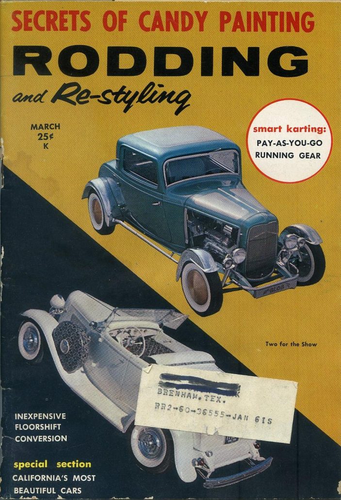
Nifty Shifting by Ed Lenon
When Oliver Hine isn’t building a rod (R&R, April 1959), “Hine’s Varieties”) or off copping a Best-in-Show trophy somewhere, you can bet your fan belt he’s probably up to one of his old tricks – namely, conjuring up a new adaptation that will serve rodders in good stead.
Hine’s latest brainchild is, to be sure, a good bet. The Charlotte, Michigan mechanic has come up with a neat floor shift setup made to fit any column shift car with two selector arms on the transmission. What’s more the stint should prove especially appealing to rodders whose funds are more limited than their energy.
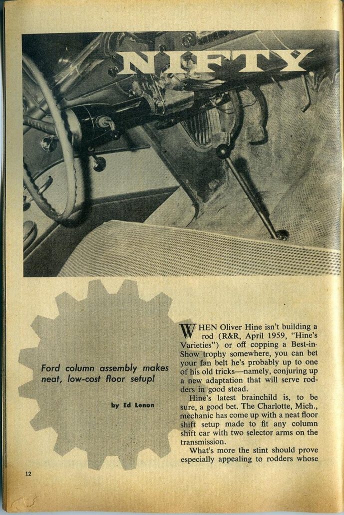
Any post-’40 Ford column shift assembly – readily available from the local junk yard – can be used for the conversion. Also, needed are a hacksaw, welding equipment and a 3 or 3 and ½ inch U-clamp, depending on where the floorshift assembly is to be mounted on the transmission tail shaft.
When purchasing the assembly, make sure it is complete as shown in Photo 1.
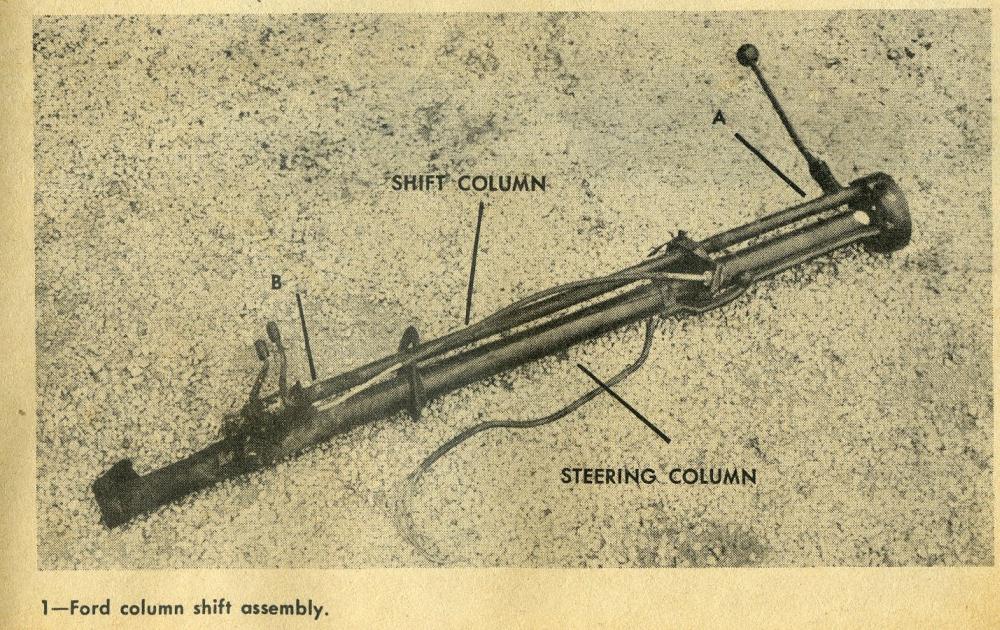
PHOTO 1
The first step is to unbolt the shift column from the steering column and cut the shift column just below the stick at point A, and about ½ inch above the shift arm bracket at point B.
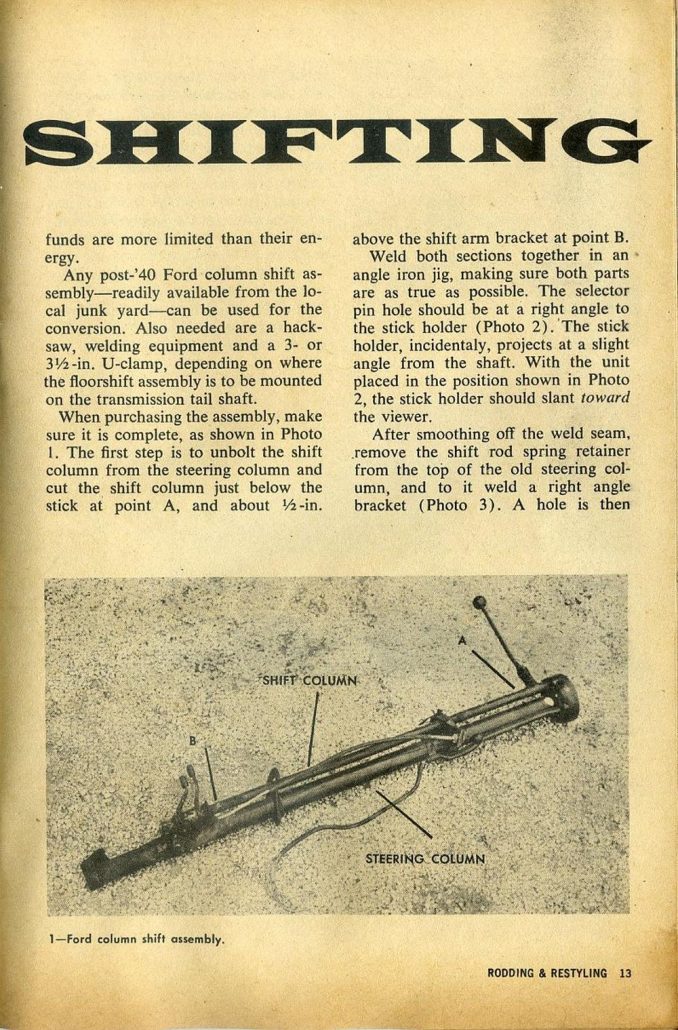
Weld both sections together in an angle iron jig, making sure both parts are as true as possible. The selector pin hold should be at a right angle to the stick holder (Photo 2).

PHOTO 2
The stick holder, incidentally, projects at a slight angle from the shaft. With the unit placed in the position shown in Photo 2, the stick holder should slant toward the viewer. After smoothing off the weld seam, remove the shift rod spring retainer from the top of the old steering column, and to it weld a right angle bracket (Photo 3).
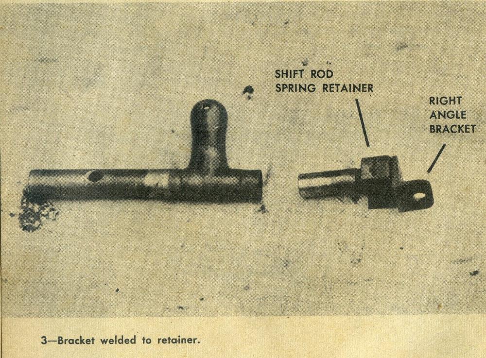
PHOTO 3
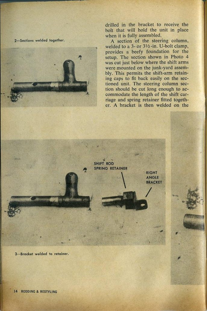
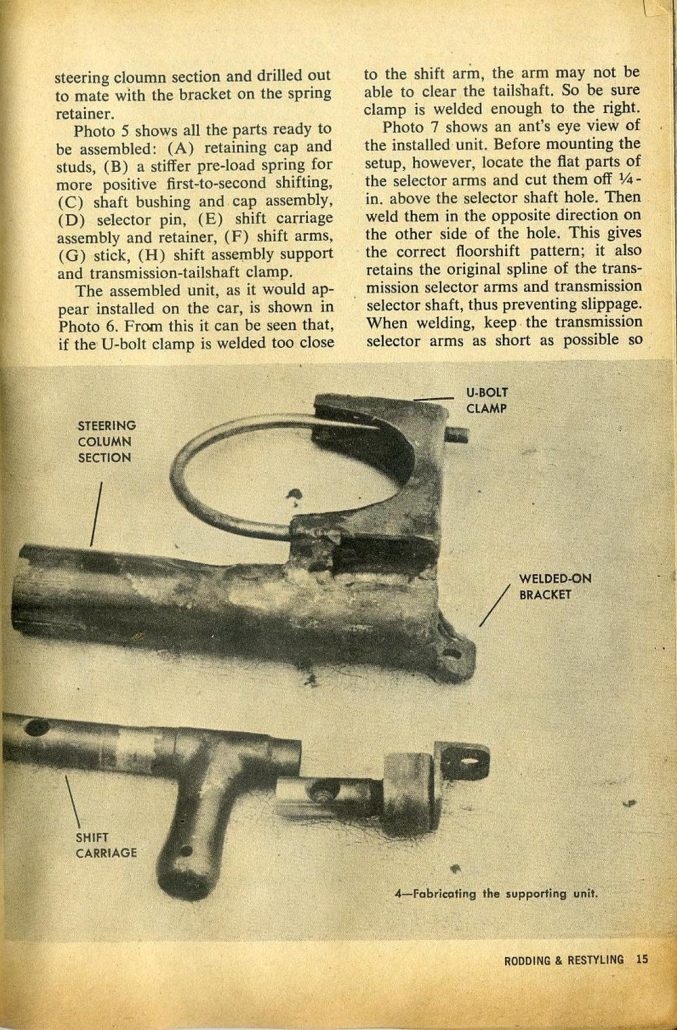
A hold is then drilled in the bracket to receive the bolt that will hold the unit in place when it is fully assembled. A section of the steering column, welded to a 3 or 3 and ½ inch u-bolt clamp, provides a beefy foundation for the setup. The section shown in Photo 4 was cut just below where the shift arms were mounted on the junkyard assembly.
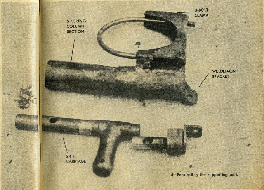
PHOTO 4
This permits the shift-arm retaining caps to fit back easily on the sectioned unit. The steering column section should be cut long enough to accommodate the length of the shift carriage and spring retainer fitted together. A bracket is then welded on the steering column section and drilled out to mate with the bracket on the spring retainer.
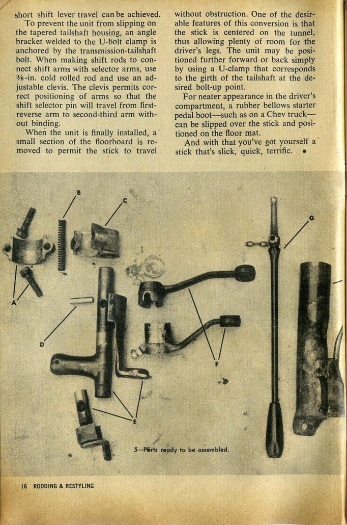
Photo 5 shows all the parts ready to be assembled:
- retaining cap and studs
- a stiffer pre-load spring for more positive first-to-second shifting
- shaft bushing and cap assembly
- selector pin
- shift carriage assembly and retainer
- shift arms
- stick
- shift assembly support and transmission-tailshaft clamp
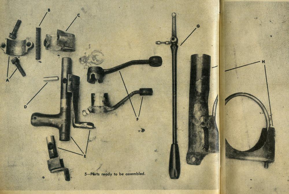
PHOTO 5
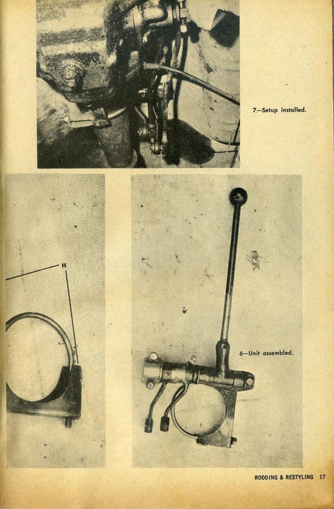
The assembled unit, as it would appear installed on the car, is shown in Photo 6. From this it can be seen that, if the u-bolt clamp is welded too close to the shift arm, the arm may not be able to clear the tailshaft. So be sure the clamp is welded enough to the right.
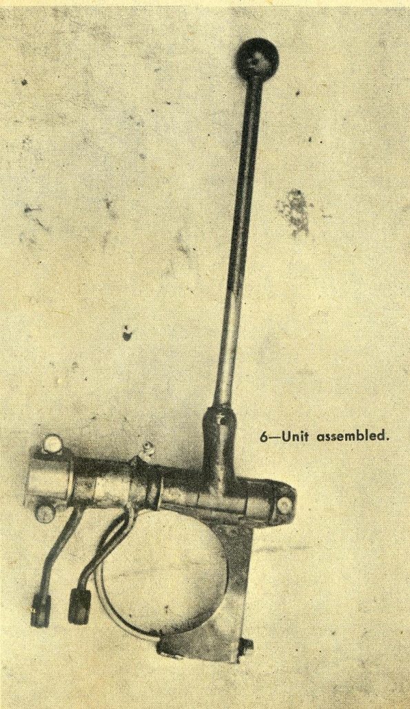
PHOTO 6
Photo 7 shows an ant’s eye view of the installed unit. Before mounting the setup, however, locate the flat parts of the selector arms and cut them off ¼ inch above the selector shaft hole. Then weld them in the opposite direction on the other side of the hole. This gives the correct floorshift pattern; it also retains the original spline of the transmission selector arms and transmission selector shaft, thus preventing slippage. When welding, keep the transmission selector arms as short as possible so short shift lever travel can be achieved.
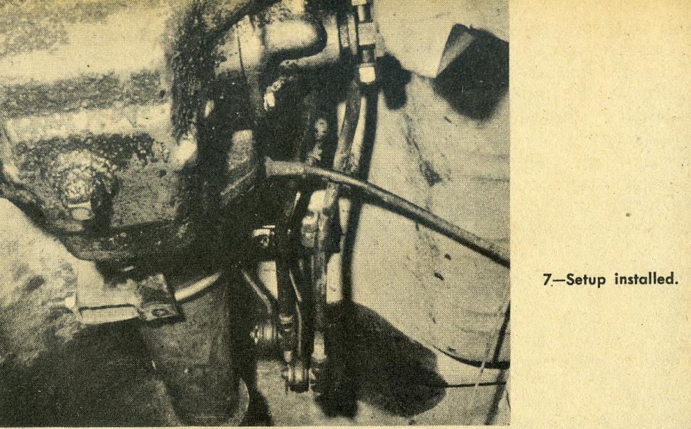
PHOTO 7
To prevent the unit from slipping on the tapered tailshaft housing, an angle bracket welded to the u-bolt clamp is anchored by the transmission-tailshaft bolt. When making shift rods to connect shift arms with selector arms, us 3/8 inch cold rolled rod and use an adjustable clevis.
The clevis permits correct positioning of arms so that the shift selector pin will travel from first-reverse arm to second-third arm without binding. When the unit is finally installed, a small section of the floorboard is removed to permit the stick to travel without obstruction.
One of the desirable features of this conversion is that the stick is centered on the tunnel, thus allowing plenty of room for the driver’s legs. The unit may be positioned further forward or back simply by using a u-clamp that corresponds to the girth of the tailshaft at the desired bolt-up point.
For neater appearance in the driver’s compartment, a rubber bellows starter pedal boot – such as on a Chevrolet truck – can be slipped over the stick and positioned on the floor mat. And with that you’ve got yourself a stick that’s slick, quick, terrific.
DOES IT WORK?
Yes it does.
Great friend and master fabricator Ben Emerson converted a column shifter to a floor shifter as part of the restoration of our 1937 Gougeon Streamliner. We had some challenges because this car is actually a mid-engine car with the shifting mechanism in front of the engine/transmission, but this involved just a reversing of the mechanism described in this article.
But the good news was that we followed this article and the shifting mechanism worked – and is period correct for installation in a 50s type sports car build. Go get ’em fiber-gang!
Summary:
Great thanks goes to Mike Wittman for sharing this “how-to” article – something he has used as a reference on how to convert a column shifter to a floor shifter since the magazine article came out in 1960.
Hope you enjoyed the story, and remember gang…
The adventure continues here at Forgotten Fiberglass.
Geoff
Pingback: My Homepage
I like that this guide shows so many pictures of welded metal. If the weld is strong, it will hold for a long time. I used to weld in high school, and I wasn’t too bad at it. I enjoyed it, but have never done it since then.
And for those of us in the ’70’s- SparkOmatic, Hurst Master Shifter and Mystery Shifter, and a couple others I’ve forgotten. I did mostly Chev conversions, but did one ’72 Ford Galaxie with a straight six and a “bolt action” that I used a muffler clamp to attach to the tailshaft with the threaded ends attached at a right angle to secure the shifter plate..
I have to admit I did nt “get” all the nuances/details in the article but thats just me…BUT I get the idea and loved the article!
I built one when the magazine came out. It was when I was putting an Olds 303 in my Model A roadster. Before I installed it I bought a new 1956 Corvette shifter for $16 at a Chevrolet dealer. The Ardun G2 has one build out of Model A transmission top. Plus Allard designed one that others have copied and seems to work well. In the caseof my Model A, I used a 1950 Olds side shift 3 speed – a basic 1938 LaSalle design. Some call these remote shifters.
Great article Geoff. Sometimes we forget just how inventive “Hot Rodder engineers” could be back when you couldn’t just go to a catalog or the internet. We actually “made” the stuff we needed!
@ Joel – great point. I have that article too, but as I recall it only has 1-2 photos. I love the images on this article so I thought it would be good to put it out to the FF gang. Should we run the other article too? You think it has additional detail others would want? Thanks for chiming in my friend. Geoff
The January 1954 issue of road and track magazine shows how to do this as well. Not as detailed but an image if this. It also shows how to make first gear synchronized in a Ford gear box.